 |
| Home |
| Assembly Notes |
| More Speed |
| More Power |
| An Accurate Speedometer |
| Relocate Controller |
| 72 Volt Mod. |
| Technical Notes |
| My Repair Record |
| Environmental Issues |
| Michigan Moped Law |
|
|
After implementing the shunt mod on my bike, and adding one battery to get my voltage up to 60 volts, my top speed on level ground was between 23 and 24 miles per hour. My commute to work takes me over roads which have a speed limit of 35 mph, and a short section that is 45 mph. Since the maximum legal speed for a moped in Michigan is 30 mph, I decided to increase my total battery pack to 72 volts. My calculations lead me to believe that this would put my top speed at around 28 mph.
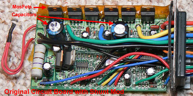
To begin, I ordered parts from Digikey. From reading posts on VisForVoltage.org, I knew that I would need to replace the 6 Mosfets in my controller with components capable of handling the increased voltage. Thanks to VIsForVoltage.org, and it's contributors, I had a part number for those mosfets. I also needed two 470uf capacitors which would handle the higher voltage, and these I could also order from Digikey. Since I have two controllers I ordered parts for both. Here is what my order looked like:
10 - P5850-ND - Cap - 470UF 100V Electrolitic NHG Radial
14 - IRFB4110PBF-ND - MOSFET N-Chan - 100V 180A TO-220AB
I ordered 10 caps to get the price break, and two extra Mosfets just in case I broke leads or otherwise fried one or two. My total was $64.82, but remember, that's for two controllers.
Upon
disassembling the controller, I found that I would need new insulators
for the MosFets, since the insulators are glued to the old ones. I
ordered these from another source, at 20 for $2.50. I also went by
Radio Shack and got a small roll of Solder Wick, which is mighty handy
for removing solder from PC boards. With all my parts in hand I began
my mods.
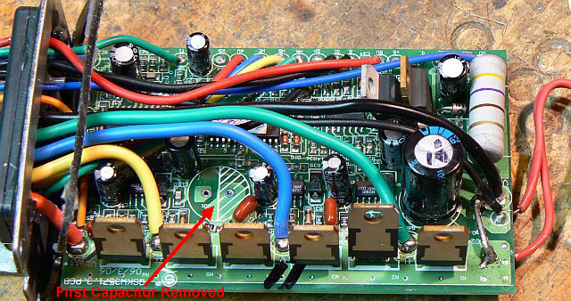
With
the case off of the controller board, I began unsoldering the parts
that needed to be replaced, starting with the 470uf capacitors. 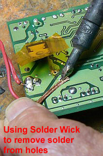 Since
all the power components are mounted to portions of the circuit board
that carry high current, my 40 watt soldering iron would not furnish
enough heat to desolder the parts. I had to resort to a 100W soldering
gun. A 60 watt Iron would have been perfect, but I made do with what I
had. The Solder Wick helped me to wick the solder out of the
feed-thru holes, and I only messed up one of the holes that fed the
gate of one of the Mosfets. If you are doing this, here is a good tip.
Use a high wattage soldering iron to desolder the drain and source pins
of the Mosfets, but use a lower wattage iron to desolder the gate lead.
Since
all the power components are mounted to portions of the circuit board
that carry high current, my 40 watt soldering iron would not furnish
enough heat to desolder the parts. I had to resort to a 100W soldering
gun. A 60 watt Iron would have been perfect, but I made do with what I
had. The Solder Wick helped me to wick the solder out of the
feed-thru holes, and I only messed up one of the holes that fed the
gate of one of the Mosfets. If you are doing this, here is a good tip.
Use a high wattage soldering iron to desolder the drain and source pins
of the Mosfets, but use a lower wattage iron to desolder the gate lead.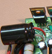 (The gate lead is the one that has the thin printed circuitry goint to
it.) It is very easy to overheat the circuit board, and your solder
sucker can then pull the plated-thru holes right out of the board. When
that happens, you will have to use some ingenuity, and some very fine
wire to repair the circuit board, and furnish a new circuit path to the
gate of the MosFet.
(The gate lead is the one that has the thin printed circuitry goint to
it.) It is very easy to overheat the circuit board, and your solder
sucker can then pull the plated-thru holes right out of the board. When
that happens, you will have to use some ingenuity, and some very fine
wire to repair the circuit board, and furnish a new circuit path to the
gate of the MosFet.
I forgot to mark which side of the capacitors were the plus side. Quick thinking though, and I figured out that I could use an ohmmeter to test for continuity between the capacitor mounting holes and the black ground wires soldered into the board. (The black wires are all connected to Battery Minus, which corresponds to the negative side of the caps)
I
put the new capacitors in first. They could not be mounted vertically
on the circuit board, due to their greater height. I had to mount them
so they could be laid over on their side. (see photo below) I then
soldered the new Mosfets into place. 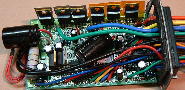
When
that was all done, I used vinyl pool-patching cement to glue the
insulators onto the Mosfets, and I also glued the clamping bar to the
back side of the Mosfets to make re-assembly easier.
Before putting the board back into the enclosure, I did a quick test. I applied 38 volts to the circuit from a power supply that could furnish 1 amp. When I turned it on, the current drain was less than 100ma, so I figured I hadn't made any obvious solder bridges, or installed a capacitor backwards.
Next I removed the seat from my bike and connected the modified controller in place of the old one. I plugged in the battery pack, turned on the key, twisted the throttle, and the wheel spun. I took the bike for a test ride. On level road, the speed was the same as before the mod... 23.8 mph at 60V. Now to add another battery.
Before adding the 6th battery to the bike to up the voltage to 72 volts, I knew I would have to make some arrangements that would limit the voltage going to the DC-DC converter. Many of the posts I have read on VisforVoltage.org tell of ruining this converter by applying too much voltage to it. On the other hand, I didn't want to spend the bucks to buy a higher rated DC-DC converter. At first I thought I would just connect a diode array between the 72 volts supplied by the ignition switch, and the input to the converter. 15 rectifier diodes in series would provide a 12.8V drop, which would be enough to stay within the specs of the converter. But what if I switched to 48 volts? Would 36 volts be enough to power the converter? I decided on another method.
In the normal wiring of the bike, battery power is supplied to the ignition switch by an orange wire that comes out of the controller. When the ignition switch is on, this power is supplied to the DC-DC Converter, and to the Power Meter on the instrument cluster. By disconnecting the orange wire from the controller and connecting the ignition switch directly to the 48 V battery, I'm able to accomplish two things. First, the DC-DC converter is supplied with only 48V, so it won't get blown by overvoltage. Second, the Battery meter will not need modification in order to read the correct state of charge for the battery. The only drawback is that now, two of the 6 cells are not being monitored by the battery meter, but that's not so bad if from time to time, you check the balance of the cells with a voltmeter.
As of this writing, I have not received my two 12V, 18AH batteries. I'm currently using 9AH batteries, which I know will not last long, but for testing they are OK. My new top speed on level ground is 28MPH.