 |
| Home |
| Assembly Notes |
| More Speed |
| More Power |
| An Accurate Speedometer |
| Relocate Controller |
| 72 Volt Mod. |
| Technical Notes |
| My Repair Record |
| Environmental Issues |
| Michigan Moped Law |
|
|
The Controllers on the X-Treme Bikes contain circuitry which limits the amount of current that can be sent to the motor. This circuitry serves to protect both the controller and the motor. In doing so, it also limits the hill-climing ability of the bike to such an extent that it becomes dangerous to drive the bike up even very slight grades in heavy traffic. In most states, these bikes need not be registered, but are street legal, and in most cases cannot legally be driven on sidewalks. Increasing the available torque therefore becomes a necessity if the bike is to be used for common adult tasks like commuting to and from work, short grocery store trips, and just visiting friends in nearby suberbs.
Here are my step by step instructions for doing what has been reffered to as the "Shunt Mod" on an X-Treme XB500 Electric Bike. My method is similar to that which is described by "hyperob" on the forum www.visforvoltage.org. His step by step instructions appear at http://visforvoltage.org/forum/3990-xb600-quotshunt-modquot-instructions.
Since the XB-500 and XB-600 controllers are not the same, I decided it would be helpful for others if I documented the steps I took to do the modification on my bike.
I have had my XB500 for about a month now, and I decided to order an extra controller for my bike, rather than take the chance of putting my bike out of comission by some mistake I might make while doing the modification. Let me preface by stating that I am a retired Electrical Engineer who work my way up from Electronic Technician to Electronics Design Engineer, so I have had a great deal of soldering experience, and circuit board design and repair. If you are going to attempt this mod, and you haven't done any soldering, I would suggest you find a local computer shop and ask one of the good techs to teach you how to solder correctly.
So lets get started. First, unplug your battery by pulling out the
battery box plug which is found underneath 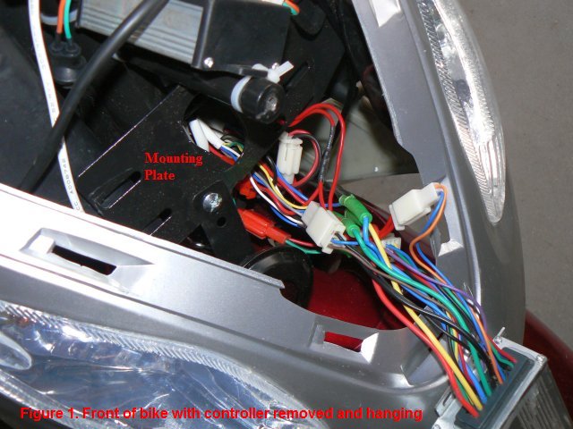 the bike just forward of the right
pedal socket. Once the battery is disconnected, turn the key to the ON
position and pull the brake pedal to discharge all the capacitors in the
system. This will not fully discharge everything, but it will get the
charge low enough to help eliminate sparks when you make connections to
the controller. Now turn the key off and remove it.
the bike just forward of the right
pedal socket. Once the battery is disconnected, turn the key to the ON
position and pull the brake pedal to discharge all the capacitors in the
system. This will not fully discharge everything, but it will get the
charge low enough to help eliminate sparks when you make connections to
the controller. Now turn the key off and remove it.
To get to your XB500 controller, you must remove the front plastic shroud that holds the front running light. This is done by removing the machine screw in the middle of the front shroud, and four sheet-metal screws in the upper part of what I call the "glove compartment" shroud. When the front shroud is loose, reach inside and pull out the headlight bulb, and then you can remove the shroud and set it aside. Immediately you will see the controller attached to a black mounting panel, with all the wires coming out of it at your right hand side. One or more screws may hold the controller to the mounting plate, and there will probably be a ty-wrap also around the controller and around the wire bundle. Remove the ty-wraps and the screws, being careful to catch the nuts and washers which are at the back side of the mounting plate and very hard to get to.
Now you must disconnect all the connectors which go to the controller. It's important to make some notes at this point. Write down a list of the wire colors on the connectors that come from the control box, and note which color wires from the bike are connected to them. There are likely to be wires that are different. For instance, my old controller had a purple wire coming from it, and it was connected to a white wire in the bike wiring. The new controller did not have a purple wire, but when I had connected all the rest of the wires, there was a white wire left over coming from the controller, so by deduction, I connected the white controller wire to the white bike wire. Luckily, it was the correct hookup, and my speedometer worked.
Next we must open the controller. There are four screws on each end of
the controller which hold the two end plates to the box. Remove all four,
and if necessary, cut away the silicone insulation material so that the
end plates can be separated from the box. Remove the blank end plate
first and set it aside. 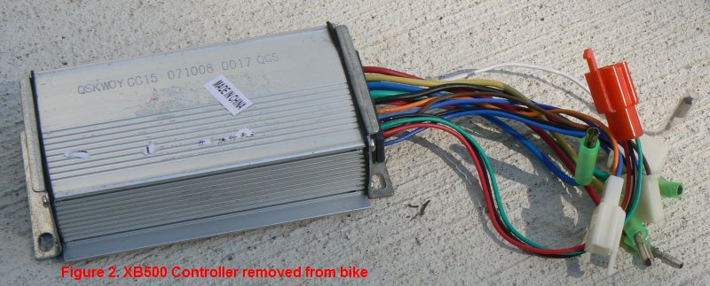 You will then
be able to see inside the box.
You will then
be able to see inside the box.
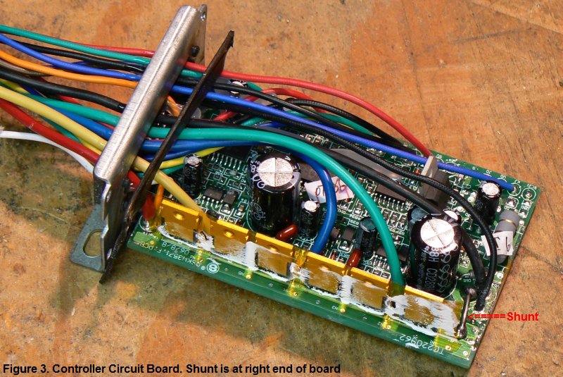
With the circuit board out of the box, locate the shunt. You will find it at the end of the board opposite where the wires enter. The shunt is a thick piece of wire connecting the negative lead from the battery to the emitters of the MosFets. Figure 3 shows the position of the shunt. I originally wanted to remove the shunt and measure it's resistance, but after several tries with a solder-sucker trying to get it out of the board, I finally gave up, and decided to leave it in place and simply add a 3 inch piece of coat hanger wire in parallell with the existing shunt.
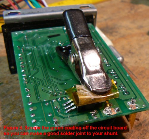
I also decided not to drill holes through the board, but to just surface solder my shunt to the circuit board. The easiest way to do this is on the bottom of the board. There is a fairly large surface at each end of the shunt where the wire may be attached. But first, you must scrape the green coating off of the board so your shunt and the solder makes good contact with the copper circuitry. There is a piece of insulator material attached to a voltage regulator on the bottom of the board which is in the way. I held this back with a clamp while I did my work. See Figure 4.
 As I said earlier, I made my shunt from a piece of coat
hanger wire. I used a really cheap coathanger, made of thin steel wire. I
measured the thickness to be 0.076 inch, which corresponds to 12.5 gage
wire. This wire has a resistance of 10.6 ohms per 1000 feet, so my 3
inch section would be about 0.0026 ohms. (I didn't figure this out until
after the fact.)
As I said earlier, I made my shunt from a piece of coat
hanger wire. I used a really cheap coathanger, made of thin steel wire. I
measured the thickness to be 0.076 inch, which corresponds to 12.5 gage
wire. This wire has a resistance of 10.6 ohms per 1000 feet, so my 3
inch section would be about 0.0026 ohms. (I didn't figure this out until
after the fact.)
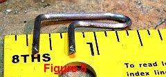
 I bent my wire loop so that it would fit
inside the controller box without the risk of touching the metal box or
any of the other circuitry on the board. Figure 5 shows the shape of my
shunt. Once I had it bent to shape, I filed down the side that would come
in contact with the circuit board so there would be good contact between
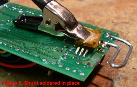
the board and the wire. I used a clamp to hold one end of the shunt wire
in place while I soldered the other end. Then I removed the clamp and
soldered the remaining end to the board. You can see how it turned out in
Figure 6.
I bent my wire loop so that it would fit
inside the controller box without the risk of touching the metal box or
any of the other circuitry on the board. Figure 5 shows the shape of my
shunt. Once I had it bent to shape, I filed down the side that would come
in contact with the circuit board so there would be good contact between
the board and the wire. I used a clamp to hold one end of the shunt wire
in place while I soldered the other end. Then I removed the clamp and
soldered the remaining end to the board. You can see how it turned out in
Figure 6.
I used a 100 watt soldering gun to solder the shunt to the board, and I made sure there was enough heat to cause the solder to flow freely around the shunt and to cover the clean part of the circuit board where I had cleaned away the coating, and I made sure the shunt would not break away from the board from vibration. The rest of the job consisted of re-inserting the board into the case and securing it in place. I put lots of silicone grease on the MosFets to insure that they would be properly heat-sinked to the case. It wasn't easy to line up the clamping bar so I could get the screws to go back into the holes in the bar, but with a pair of needle-nosed plires, I was able to eventually line up one of the screws and get it started into the clamping bar. The other two screws were much easier to line up once the first one was started and acted as a guide for the rest.
I put a thin layer of silicone sealant on the rubber gaskets before screwing the end caps onto the controller housing. I also put dabs of sealant over the heads of the three screws which hold the MosFets against the side of the case. Finally, I reinstalled the controller into the bike, making sure all the connectors went to the right wires. Then came the moment of truth.... re-connecting the battery. When I plugged the connector into the battery, I could hear that there was a spark, but that's farily normal when connecting a battery to any circuitry. I turned the key to the ON position. There was no smoke. The controller didn't get hot. So far, so good. Then with the bike up on the stand and the rear wheel off the ground, I twisted the throttle. The rear wheel spun!
To make it easier to re-mount the controller to the mounting plate, I drilled two small holes in the mounting plate to line up with the top mounting holes of the controller, and used sheet metal screws to secure the controller in place. There just isn't enough room to hold a washer and nut in place for a machine screw.
**** UPDATE **** 10/01/2008
After doing some testing on my bike, I found that the stock controller on an XB-500 limits the motor current to 15 amps, and that the voltage drop across the shunt wire is 50 MV. That would mean that the resistance of the shunt is 0.0033 ohms. Taking these measurements into consideration, I calculated that my modification effectively bypasses the current limiter, and allows the controller to pass as much current as the battery and circuitry of the bike can furnish. Knowing this, I decided to re-do my shunt mod and place the proper parallel resistance into the circuit to allow 25 amps of current. That would mean that my total resistance would have to be 0.002 ohms. To achieve this, I need to place 0.00508 ohms in parallel with the shunt.
I decided instead of the coat hanger, I would use wire of known resistance... common steel electric fence wire. This can be bought at Home Depot in various sizes. 16 gage steel wire has a resistance of 26.5 ohms/1000 feet, or .0022 ohms/inch. So we will need 2.3 inches for our shunt. I cut my piece of wire 2.7 inches long to allow 0.2 inches on each end to solder it to the circuit board.
After replacing my coat hanger shunt with my 16 gage steel wire shunt, I went out and measured the current that my bike would draw, and sure enough, it limited the current to 24.8 amps.