 |
| Home |
| Assembly Notes |
| More Speed |
| More Power |
| An Accurate Speedometer |
| Relocate Controller |
| 72 Volt Mod. |
| Technical Notes |
| My Repair Record |
| Environmental Issues |
| Michigan Moped Law |
|
|
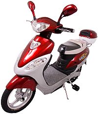
Over the winter, I had my XB-500 in my basement. I wanted to do some testing with other controllers, but most of all, I wanted to change the location of the controller so it was closer to the motor. Why, you ask?
For me, the biggest reason was to gain efficiency by eliminating voltage drop over long wires. In the original configuration, the controller is located in the front shroud of the bike, the battery is in the middle, with it's connector facing back, and the hub motor is, of course, located at the rear. That means that wire has to carry high current from the battery up to the the controller, and then from the controller back to the motor, and from the motor back to the controller.
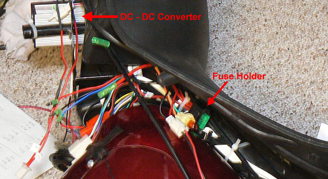
By locating the controller between the battery pack and the motor, we can eliminate almost 4 feet of 14 gage cable from battery to controller, and an additional 5 feet of cable from controller to motor. The battery cable is 14 gage wire, and the 3-wire motor wiring is 16 gage. When we are drawing 15 amps from the battery, the 4 feet of battery cable drops about 0.36V, while the motor cable drops an additional 1.1V. Not a lot, but it does amount to over 1/2 mph, and when we're going up hill and drawing more current, it's an even bigger factor. A plus was that while doing the re-wiring, I would be able to locate the 30 amp fuseholder conveniently under the seat, making it much easier to change a blown fuse. I decided to also add a switch so I could choose between 48V and 60V power.
I
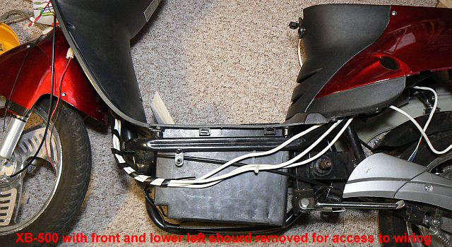
started by removing the front shroud and lower left panel from the
bike, which gave me access to all the wiring between the under-seat
area and the front of the bike. I removed the controller, and separated
the various wires between underseat and front shroud. I then drew up a
new wiring diagram with front-of-bike items located at the top, and
rear-of-bike items located at the bottom. I added to the diagram, the
switch, and the additional battery.
I
completely removed the cable from the battery to the front of the bike,
along with the house-shaped connector that plugs into the battery pack.
The fuesholder came off along with the cable. I cut the cable down to
18 inches for the red wire, and 12 inches for the black wire.
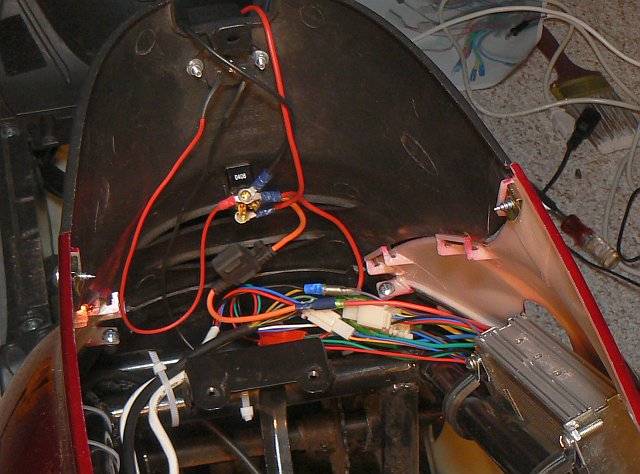
I
mounted a SPDT switch under the front edge of the seat, and brought the
red wire from the battery up to one contact of the switch. This is the
switch that allows me to switch between 48V and 60V. I also used this
terminal of the switch as a junction point for the charger plug and the
additional battery. I connected one end of my new fuseholder to the
wiper contact of the switch. The black wire, I routed so that it would
be accessible to my new controller location, to the right of the
under-seat conpartment. To secure the controller in place, I used two
rubber-covered C-clamps. The controller sits between the side body
panel and the frame member to the right of the seat compartment.
There was a 5 conductor cable that originally ran from the controller to the motor hall-sensors. With the controller located in the under-seat area, the hall-sensor from the motor could be connected directly to the controller. I left the 5 conductor cable in place, and used it to carry signal from the throttle and the brake switches to the controller.I added additional wires to bring battery voltage, ground, and speedometer wire up to the ignition switch and instrument panel.
 Finally,
when all the wiring was complete and tested, I put new ty-wraps on the
cables leading from the back to the front to keep them tidy and in
place. Before re-installing the body panels, I plugged in the battery,
turned on the ignition, and made sure the motor would turn.
Finally,
when all the wiring was complete and tested, I put new ty-wraps on the
cables leading from the back to the front to keep them tidy and in
place. Before re-installing the body panels, I plugged in the battery,
turned on the ignition, and made sure the motor would turn.
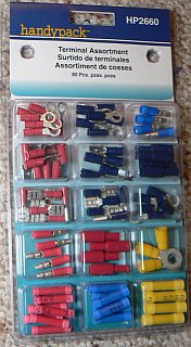
In the process of making these changes, I bought several small packs of connectors from Home Depot. I found out later on that most auto parts stores stock assortment packs of terminals. I would have been better off buying one of these, as it had all the connectors I needed, and plenty to spare, and cost less than the individual packs of each kind of connector. I didn't have to buy Ty-Wraps, as I already had a big pack from my previous experiments.
I've seen several posts on VisforVoltage.org where folks have been looking for wiring diagrams of the XB-500. I feel my own diagram is quite useful, since it's arranged similar to the bike. Below are links to the original XB-500 schematic, and to my version.