| Bergerweb Home Page |
| GM Passlock System |
| Tools and Supplies |
| 1 - Disassembly |
| 2 - Bypassing the Ignition Switch Security Circuit |
| 3 - Reassembly & Recalibration |
| Notes |
|
GM Passlock Bypass Author- Richard M. Berger 09/29/2010 All rights reserved Following the instructions in this writeup will save you over $300.00 If this article helps you fix your GM Passlock Security Problem on your Pontiac Grand Am or Alero, put two dollars in an envelope and send it to: Security Fix 1131 Outer Drive Fenton, MI 48430 |
| Bypassing the Ignition Switch Security Circuit |
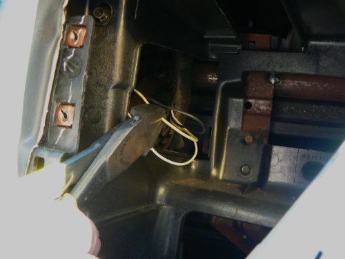
Now that you have found the Passlock II wires and gained access to them, it's time to get down to the real work of bypassing the security module so that you aren't bothered again by the blinking "SECURITY" light.
 |
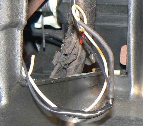
Cut the yellow wire. Leave the side that goes into the bundle as long as possible, but leave enough of the other end so you can gain access to it, in case of an emergency. Insulate the end that goes to the ignition module and push it back out of the way. |
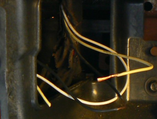 |
Strip some insulation from the end of the yellow wire that goes into the bundle. Strip away about 3/4 inch of the insulation on the black wire. If you happen to cut through the wire, that's OK, just insulate the end that goes to the ignition module and push it back out of the way. If the bare wire is not bright copper color, scrape it lightly with the knife blade to make it shiny and clean. |
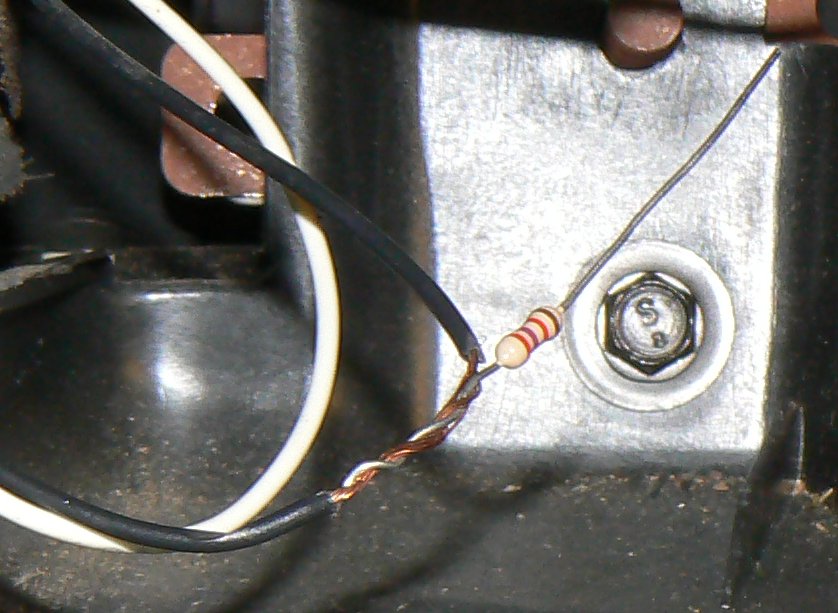 |
Take any resistor between 1500 ohms and 3300 ohms, and wrap one lead tightly around the bare part of the black wire that goes into the wiring harness. Make sure that there is good mechanical contact between the resistor lead and the copper of the black wire. Once the lead is wrapped securely, cut the excess lead off so it does not extend past the bare section of the wire. |
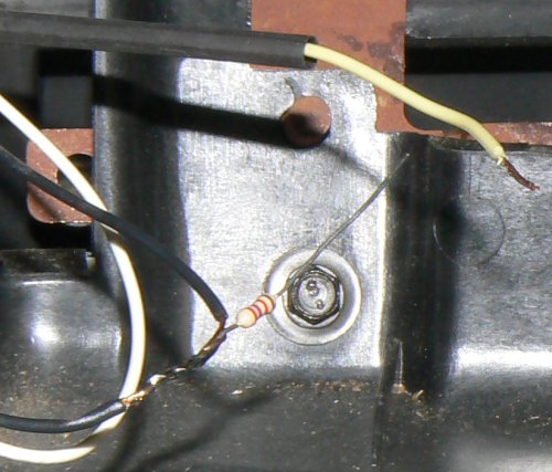 |
Heat the joint with a soldering iron and apply enough solder to cover the entire joint. Allow the heat of the iron to suck the solder into the joint. |
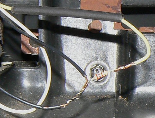 |
Slide a piece of properly sized shrink tubing over the yellow wire. Then wrap the remaining resistor lead and the stripped end of the yellow wire together tightly to make a good mechanical joint. |
 |
Heat the yellow wire and resistor lead with a soldering iron and apply solder to cover the entire joint. Be careful not to heat the shrink tubing. |
| Before continuing further, this is a good time to test the modification to make sure that it works. You may, however, have trouble getting the Alero gearshift lever into "Park" because you probably had to pull it all the way back to make room for the radio bezel and the radio. If you can, put the gearshift in Park. Make sure that none of the bare wires in the radio cavity are touching any metal parts. Remove the key from the ignition, go under the hood and re-connect the negative battery terminal. Then get back in the car, insert the Key, and try to start the car. It should start, and then stall, with the "SECURITY" light flashing. In rare cases, the car may keep running and the security light will not illuminate, but that only happens if you are very lucky. If the Security light flashes, leave the ignition in the ON position and wait at least 10 minutes. The Body Control Moudle should reprogram itself, and the "SECURITY" light should go out. When it does, Turn the ignition OFF for a few seconds, and then try to re-start the car. The "SECURITY" light should remain off this time. If not the modification has failed and you are in for some additional troubleshooting, for which you will need a shop manual. If successful, you can now disconnect the battery again and continue with the next step. | |
 |
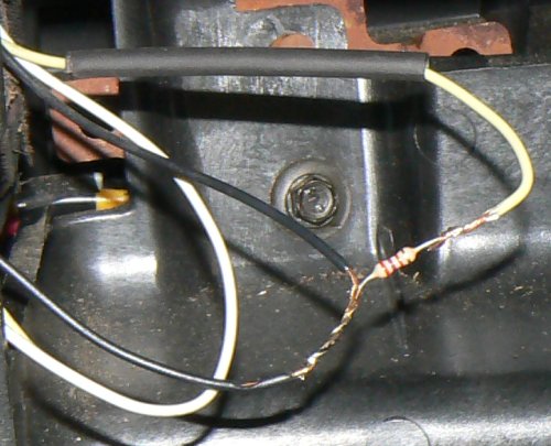
Slide the heat shrink tubing down over the resistor and heat it with a hair dryer until it shrinks tight around the resistor. Then wrap the other lead of the resistor and the black wire with electrical tape so that no bare wire is left uncovered. Carefully tuck the three wires and resistor back through the hole in the left side of the radio cavity. |