 |
| Home |
| II - Getting the Parts |
| III - Assembling it All |
| IV - Controller Programming |
| V - Test Rides |
| Cost Spreadsheet |
|
|
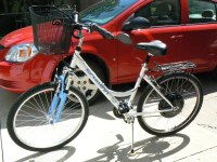
Once I had the Nine Continent Motor mounted in my bike, I took a spin around the block to see how the additional weight would effect the ride, and determine the difference in effort to pedal the bike. I found it amazingly easy to pedal the bike, even though it was noticeably harder to spin the rear wheel by hand. The motor offers a considerable amount of resistance to spinning, but it's hard to notice when you are pedaling. Also, with the added weight, the bike coasts a long way before coming to a halt.
-
Two things to consider when hooking the Kelly Controller to a brushless motor.
- Program the controller with the desired parameters
- Find the right combination of wiring between the controller and the motor
Programming the Controller
The interface program that allows a PC to communicate with the Kelly Controller is available on their web site. It can be downloaded and installed on a PC. Your PC must have an RS-232C Port available, as that is the interface provided on the controller. If your PC doesn't have an RS-232C port, there are many companies on the internet where you can purchase a USB to RS-232C adapter. I bought two for my laptop at a cost of just over $7.00. The installation of the program places an Icon on your desktop labeled "Kelly KBS User Program" The Controller must be powered on when you launch the program. If not, you will get a message that it could not find a controller.
For my first test, I hooked my 48 volt battery pack to the controller... Minus to the big black power wires, Plus to the big red power wires. I connected the controller's hall sensor wires to the motor hall wires according to the color code. Then I also applied the +48 volts from the battery to the controller's Pin 7 (pink), which is the controller's on/off control line. I double clicked the User Program Icon on my PC desktop, and got this message:
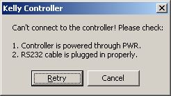
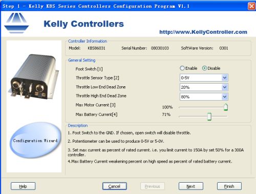
Of course, dummy.... You forgot to connect the serial cable to the controller. I hustled down to my basement and found a 12 year old serial interface cable with 9-pin D connectors on both ends. Back out to the garage, I plugged it into my PC, plugged the other end into the 9-pin connector on the Kelly Controller, and powered up again. This time when I launched the Kelly User Program, I got the first programming screen:
-
On this screen, I set the parameters as follows:
- Foot Switch = Disable (I don't have a foot switch)
- Throttle Sensor Type = 0-5V
- Throttle Low End Dead Zone = 20% (The defalt setting)
- Throttle High End Dead Zone = 80% (The default setting)
- Max Motor Current = 50% (I wanted a limit of 25 amps on a 50 A controller)
- Max Battery Current = 100% (I'm still not sure what this means)
Each screen of the user program has a brief description of each of the controls on that screen. Let's proceed...
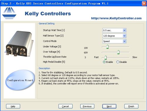
This screen sets up a few control parameters, and allows you to control how the unit protects your battery from overvoltage, and excessive discharge.
-
Here are my settings for the second screen:
- Startup Wait Time = 0.5 sec (default setting)
- Hall Sensor Type = 120 degree (I don't know how to tell which is correct)
- Control Mode = Speed (Choices are Speed, Torque, and Balanced)
- Under Voltage = 42V (10.5V per SLA pack)
- Over Voltage = 60V (15V each battery)
- Throttle Up/Down Rate = 3 (Not sure what this does)
- High Pedal Disable = Enable (A nice safety feature)

You can set up a few control functions here. I left them all as they were except I enabled the "Half Current On Reverse", even though I don't have a reversing switch.
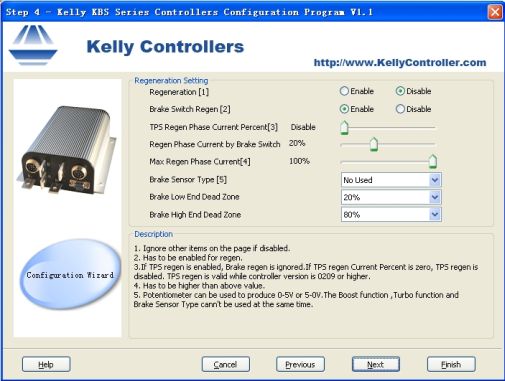
This screen sets up parameters for braking and regeneration. The controller can shut down when the brake switch is activated to insure that the motor is not working against your efforts to stop your vehicle. It can also be programmed to use the vehicle inertia to recover energy back into the battery.
-
My settings for this screen:
- Regeneration = Enable Yes. I want to conserve braking energy
- Brake Switch Regen = Enable Starts regen whenever the brake is activated
- TPS Regen Phase Current Percent = Leftmost (disable) (not using throttle for regen)
- Regen Phase Current by Brake Switch = 100% (Might as well set it as high as possible)
- Max Regen Phase Current = 100% (Max this out also)
- Brake Sensor Type = Not Used (Not using proportional braking)
- The rest of the settings aren't used
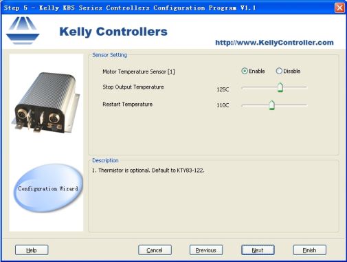
The controller can monitor the motor temperature, and shut down when it is too hot. To use this feature, you must have a thermistor in the motor. I'm not using this function, so I have it disabled.
The sixth screen tells you to click "Finish" to write the configuration to the controller. When you do, and it successfully transfers the settings, you get this screen: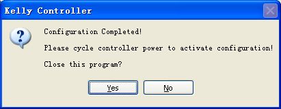
Find the Correct Wiring Combination
Brushless Motor Controllers have three power output wires, and three hall sensor input wires. Likewise brushless motors have three power input wires, and three hall sensor output wires. Most often, the power wires are color coded... blue, green, and yellow, and the hall sensor wires are also color coded the same way. You can tell which are the power wires, because they are quite thick, while the hall sensor wires are very small.
One would assume that the power wires and hall sensor wires should be hooked up observing the color codes, and in many cases, that is the case. But there is no real standard for this, and when mixing controllers from one source, and motors from another source, it's likely the color codes will not match up.
There are six possible ways of hooking the hall sensor wires to the controller inputs:
- blue-blue green-green yellow-yellow
- blue-blue green-yellow yellow-green
- blue-yellow green-green yellow-blue
- Blue-green green-blue yellow-yellow
- blue-yellow green-blue yellow-green
- blue-green green-yellow yellow-blue
I created a spreadsheet with all 36 possibilities listed, and a space for comments. I used terminal strips to connect the controller to the motor wires, and put an ammeter in series with the battery. I sat the bike on a stand with the rear wheel off the ground, and went through all 36 combinations to find the one that worked. It's important to test all the combinations. There will be three that work correctly, three that spin the motor in the right direction, but with higher current, and rough running. There will be 6 that spin the motor backwards, and the rest will either not do anything, or they will cause the motor to vibrate. As you do your testing, you must monitor the battery current. As you turn the throttle up, be careful to back off if the current starts to go above 4 amps. The correct combinations will spin the motor smoothly in the right direction, and should draw less than 4 amps with no load.
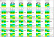 Click Here for the spreadsheet
Having tested all combinations, I wired the motor and controller to the first of the three good ones, and then took the bike out for a short test ride.